EXAMINATION : ELECTRONICS
1. What is the resistance value of this resistor:
10 k ohm
2. This resistor has the value of 68 k ohm. Which color code will you put on the different color-rings:
blue , gray , orange
3. Which electronic component is this graphical symbol illustrating:
Resistance, 3300 ohms
4. Which electronic component is this graphical symbol illustrating:
Capacitor
5. Which electronic component is this graphical symbol illustrating:
Potentiometer, 10 kilo-ohms
6. Which electronic component is this graphical symbol illustrating:
Transistor
7. Which electronic component is this graphical symbol illustrating:
Zener diode
8. Which electronic component or system of components is this graphical symbol illustrating:
Operational amplifier
9. Which electronic component or system of components is this graphical symbol illustrating:
Bandpass filter
10. Which electronic component or system of components is this graphical symbol illustrating ?
Inverter
11. The figures show a graphical symbol for a particular electronic component and a typical working characteristic for the same component. Which component?
Silicon controlled rectifier (SCR)
12. The figures show a graphical symbol for a particular electronic component and a typical working characteristic for the same component. Which component?
Triac
13. The figure shows a silicon controlled rectifier with a RC circuit connected in parallel. RC circuit is often used in such connection. For which purpose?
Protect the SCR against damage caused by high voltage spikes
14. The figures show a graphical symbol for a particular electronic component and a typical working characteristic for the same. Which component?
Transistor
15. The circuit symbol is a driver for a solenoid (coil) of a solenoid valve S. What is the purpose of the diode IN 4002 connected in parallel to the solenoid S?
Blocking inductive kick from the solenoid
16. This is a typical emitter follower. What is the main benefit obtained by use of an emitter follower?
The input impedance is made much larger than the output impedance
17. Ordinary thyristors (SCR) must often be protected against reverse overvoltage transients because even over-voltages of extremely short duration can destroy them. These circuits have been given such over-voltage protection, but only one of them is correct. Which?
Figure 1
18. Diodes are widely used in rectification, or the conversion of alternating current to direct current. This circuit symbol is such example. The input voltage V(in) is sine-wave AC. Which of the shown output voltages is correct for this circuit?
Figure 1
19. The circuit symbol is a widely used system for rectification of AC into DC. Which of the diagrams is the correct for the out- put voltage when the input voltage is sine-shaped as shown?
Figure 1
20. The circuit symbol is a widely used system for converting AC voltage to DC voltage. In this case the input voltage is a sine-wave. Which of the shown diagrams is correct for the output voltage V(out.)
Figure 1
21. The circuit symbol is a full-wave bridge rectifier. Which electronic component will you connect between 'a' and 'b' in order to obtain reduced ripple voltage to the load RL.
Capacitor
22. This amplifier circuit is a very common configuration used to amplify the difference in voltage between two input signals; in this case input 1 and 2. What is this amplifier called?
Differential amplifier
23. Which function is this operational amplifier circuit performing?
Differentiator
24. Which function is this operational amplifier circuit performing?
Integrator
25. Which function is this operational amplifier circuit performing?
Non-inverting amplifier
26. Which function is this operational amplifier circuit performing?
Inverting amplifier
27. These circuits are all active filters. Which of the circuits is a high-pass filter?
Figure 1
28. These circuits are all active filters. Which of the circuits is a low-pass filter?
Figure 2
29. These circuits are all active filters. Which of the circuits is a band-pass filter?
Figure 3
30. An important quantity which is useful in circuit analysis is known as conductance G (Siemens). Which of the formulas A to D expresses the conductance for this circuit?
G = I / R
31. There are two fundamental laws of electric circuits.
The first states that the amount of direct current flowing away from a point in a circuit is equal to the amount flowing to that point.
The second is a confirmation of the principle of the conservation of energy and says "The difference in electrical potential between any two points is the same regardless of the path along which it is measured".
Whose laws are they?
Kirchoff's
32. Use Kirchoff's current law and Ohm's law to calculate the value of the current I for this circuit.
22 A
33. Use Kirchoff's voltage law and Ohm's law to calculate the voltage V(2) across the resistance R(2).
4,5 V
34. Find the value of the voltage drop from terminal A to terminal B in this circuit:
- 38 V
35. This circuit consists of two resistances, R1 = 6 ohm and R2 = 12 ohm , connected in series. Calculate the equivalent resistance R(S) of the two resistances.
R(S) =18 ohm
36. Choose the resistance R from the list A to D which allows highest possible current without exceeding 5W power consumption.
R(S) = 25 ohm
37. This circuit consists of two resistances, R(1)= 12 ohm and R(2) = 6 ohm, connected in parallel. Calculate the equivalent value R(S) of the two resistances.
R(S)= 4 ohm
38. This circuit consists of two capacitors, C(1) = 6 µF and C(2) = 12 µF, in series. Calculate the equivalent C(S) of the two capcitors.
C(S) = 4 µF
39. The circuit consists of two capacitors, C(1) = 6 µF and C(2) = 12 µF, in parallel. Calculate the equivalent C(S) of the two capacitors.
C(S) = 18 µF
40. The circuit consists of two inductors, L(1) = 6 H and L(2) = 12 H, in series. Calculate the equivalent L(S) of the inductors.
L(S) = 18 H
41. The circuit consists of two inductors, L(1) = 6 H and L(2) = 12H, connected in parallel. Calculate the equivalent L(S) of the two inductors.
L(S) = 4 H
42. This circuit consists of a voltage source V, a change-over switch S, a resistor R and a capacitor C. The voltage/time figures 1 to 4 show possible changes in the voltage V(C) in case the switch S is suddenly shifted from position 1 to 2 at time t = 0. Only one of the diagrams is correct. Which?
Figure 1
43. This circuit consists of a current source I, a change-over switch S, a resistor R and a capacitor C. The current/time figures 1 to 4 show possible changes in the current I in case the switch S is suddenly shifted from position 1 to 2 at time t= 0. Only one of the diagrams is correct. Which?
Figure 1
44. This circuit consists of a voltage source V, a change-over switch S, a resistor R and an inductor L. The voltage/time figures 1 to 4 show possible changes in the voltage V(L) in case the switch S is suddenly shifted from position 1 to 2 at time t = 0. Only one of the diagrams is correct. Which?
Figure 1
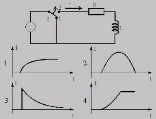
45. This circuit consists of a current source I, a change-over switch S, a resistor R and an inductor L. The voltage/time figures 1 to 4 show possible changes through L if the switch S is suddenly shifted from position 1 to 2 at time t = 0. Only one of the diagrams is correct. Which?
Figure 3
46. Wheatstone resistance bridge is often used for measuring resistances in for instance Pt 100 temperature sensors or strain gauges. This figure is such a bridge. What is the requirement for balance of such a bridge. i.e. the current through the meter i(m) = 0.
R1 / R2 = R3 / R4
47. This is a parallel L-C circuit with curve showing frequency- impedance characteristics. Which of the formulas A to D will you utilize for determining the resonant frequency f?
f o = 1 / (2 sqrt (L/C) )
48. Which function is this circuit performing?
Differentiating
49. There are many applications in circuit theory where it is important to obtain the maximum possible power that a given source can deliver. This figure consists of a practical voltage source V(g) with internal resistance R(s). A resistance R(L) will maximize the power transmission from the source to R(L)?
R(L) = R(s)
50. This circuit is a transformer with two windings, N(1) = 2000 and N(2) = 1000 turns, on a common magnetic circuit. Assume that there are no energy losses in the transformer itself. Calculate the output voltage V(2) when the input voltage is V(1) = 100 Volt.
V(2) = 50 V
51. This figure is a transformer, with two windings, N(1) = 2000 and N(2) = 1000 turns, on a common magnetic circuit. Assume that there is no energy loss in the transformer itself. Calculate the current I(2) when the current I(1) = 2 A.
I(2) = 4 A
52. A transformer with 10:1 turns ratio and rated 50 kVA, 2400/240 Volts, 60 Hz, is used to step down the voltage to a distribution system. The low tension voltage is to be kept constant at 240 Volts. What load impedance connected to the low-tension side will cause the transformer to be fully loaded?
1.15 Ohms
53. This circuit is a logic gate with two input signals, A and B, and one output signal Q. Which type of logic function is the gate giving?
OR gate
54. This circuit is a logic gate with two input signals, A and B, and one output signal Q. Which type of logic function is the gate giving?
NOR gate
55. This circuit is a flip-flop. Which type?
Bi-stable flip-flop
56. This graphical symbol is a logic gate. Which gate?
NOR
57. This graphical symbol is a logic gate. Which gate?
NAND
58. This graphical symbol is a logic gate. Which gate?
AND
59. This graphical symbol is a logic gate. Which gate?
OR
60. Transmission lines play a central role in radio frequency circuits, where they are used to pipe signals around from one place to another within a circuit, and often to an antenna system. General rules for such transmission line is that they must be "matched". Which of the cables below would you use to obtain a matched transmission between Z1 and Z2?
Figure 4
61. Radio frequency signals can carry information from one place to another if it is modulated. There are several ways to modulate a carrier. Which modulating method is illustrated here?
Amplitude modulation (AM)
62. Which cell voltage will you supply for trickle charging of a lead acid battery?
2.15 V
63. What kind of electrolyte is used for Nickel-iron batteries?
Solution of potassium hydroxide (KOH) and water
64. How can we check if a lead-acid type battery is fully charged or not?
Measure the specific gravity of the electrolyte
65. When data are to be transferred over telephone lines, we often utilize modem at each end. Which of the following adapter cards (parts) will you use for interfacing a modem to a computer?
Serial adapter
66. The powersupply to the harddisk of a personal computer consists normally of two voltages. Which?
5 V and 12 V
67. The picture shows a common used 3,5 inches diskette type for storing data. What is the data storing capacity for such diskette?
1.44 MB
68. What do you understand with a computer's POST system?
A series of tests run by the computer at power on


The companies can make strides money related precision, diminish overhead costs, and guarantee compliance with charge laws and directions. Outsourced accounting firms use progressed innovation.
BalasHapus